Robotics Motion Measurement

Robot Trajectory Measurement and Analysis

Compare observed movement with the commanded path.

Lecen’s robot trajectory measurement solution establishes external observation of tools, bodies and moving parts. Position, orientation where supported by the target setup, and time references are aligned with controller records for path deviation, repeatability and dynamic-motion analysis.

Product brand: Lecen Technology

Robot Trajectory Measurement and Analysis functional architecture illustration
Solution architecture illustration
Working scope
Tool / body trajectories
Approach
Coordinates + timestamps
Project focus
R&D and testing

Project goals

Align measurement point, coordinates and time

Commanded motion, encoder feedback and external observations are different data sources. The design places observed motion in a defined coordinate frame and time base before comparing it with reference trajectories. It supports research and validation rather than replacing the robot’s control or safety systems.

In focus

What the solution covers

Define the measured point and frame

Identify whether the task concerns the tool center, flange, body or another target. Establish the transformation from a tracked rigid target to the tool; the marker center is not automatically the required measurement point.
Evaluate position and orientation separately

Obtain outputs appropriate to the target component and geometry. Analyze translation, rotation and repeatability using documented frames, units and orientation conventions.

Align records in time

Associate external observations with controller logs and examine clock offsets and delivery latency. Matching sample rates does not, by itself, synchronize two data streams.

Preserve observations and processing methods

Record trial conditions, validity, gaps and filter settings. Retain the calculations used for velocity, acceleration or deviation so smoothed curves are not mistaken for untouched measurements.

Workflow

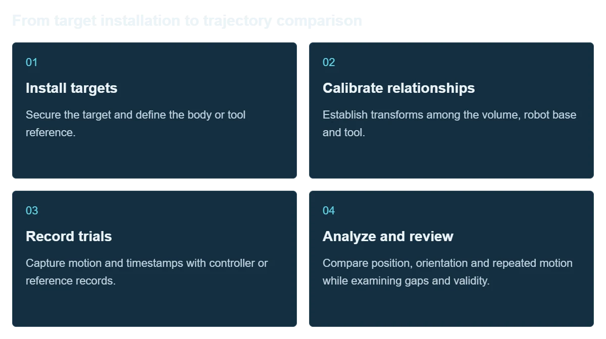
From target installation to trajectory comparison

Both spatial and temporal references are part of a measurement setup and need verification.

  1. Install targets

    Secure the target and define the body or tool reference.

  2. Calibrate relationships

    Establish transforms among the volume, robot base and tool.

  3. Record trials

    Capture motion and timestamps with controller or reference records.

  4. Analyze and review

    Compare position, orientation and repeated motion while examining gaps and validity.

Integration

Validate representative trajectories

Use directions, curves and speeds relevant to the experiment; a stationary-point check does not replace dynamic evaluation.

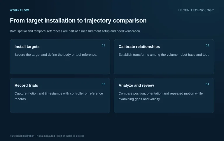
Robot Trajectory Measurement and Analysis workflow illustration
Workflow illustration

Define the test

Specify points, paths, speeds, volume and error definitions.

Plan the observation area

Arrange views and attachment around occlusion and mechanical movement.

Align space and time

Define transforms, timestamps, log association and validity handling.

Repeat and document

Preserve observations, references, processing settings and trial results.

Configuration

Architecture and planning inputs

Robot Trajectory Measurement and Analysis — Architecture and planning inputs
ObjectsTools, flanges, bodies or selected moving components
Spatial referenceMeasurement frame, robot base and tool transformations
DataPosition trajectories; orientation according to target geometry and observation
TimingCapture timestamps, trial IDs and controller-log association
AnalysisPath deviation, repeatability, dynamics and data validity
RecordsInstallation, calibration, raw observations, processing and trial results

Applications

Where it fits

Manipulator path validation

Compare executed and reference paths across representative speeds and loads.

Mechanism and parameter studies

Compare observed motion under repeatable tasks and different configurations.

Mobile robot experiments

Evaluate body trajectories within an observable test area using calibrated spatial references.

Application and workflow visuals

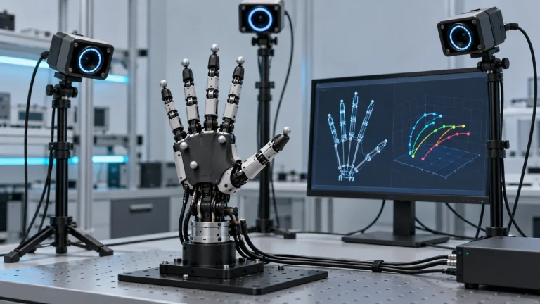
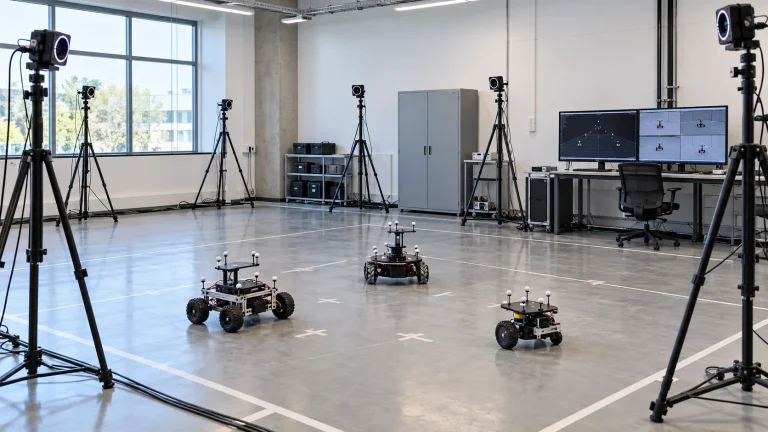
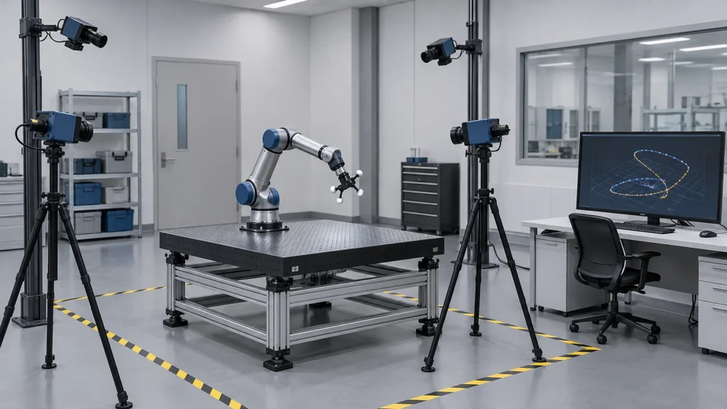
Optical robot trajectory observation laboratory concept
Optical robot trajectory observation laboratory concept; illustrates the application context.AI-generated concept, not a product test, software screenshot or customer project.

FAQ

Common questions

How does external measurement differ from encoder data?

Encoders and controllers provide internal records; external observation supplies an independent view. Align the point, coordinate frame and time before comparing them.

Is the tracked target center the tool center point?

Not necessarily. Establish and validate the spatial transformation between them.

Does a higher sample rate guarantee accuracy?

No. Accuracy, sample rate, end-to-end latency, visibility and calibration are separate characteristics to evaluate.

Can this be used in a control loop?

The scope here is external measurement and testing. Control integration requires separate timing, validity and safety-interlock evaluation and does not replace safety controls.

Does the solution name establish standards compliance?

No. Specify the standard edition, method, equipment conditions and reporting requirements, then support any claim with the corresponding test results.

Project brief

Start with a project brief

Robot and tool

Models, workspace, measured points, target placement and load.

Trajectories

Paths, speeds, repetitions and reference data.

Results

Frames, timing, output format, error definitions and reporting purpose.

Talk to Lecen

Let’s scope your project

Define targets, working volume, movement speeds and required outputs to discuss observation methods and validation.

Discuss the measurement task